Introduction
The purpose of this document is to establish a comprehensive, systematic engineering procedure for
conducting a Remaining Life Assessment (RLA) study on industrial boiler pressure parts. This
procedure applies to all high-pressure boilers that have completed 100,000 operational hours or 25
years of service, in strict compliance with global boiler inspection codes (e.g., ASME Section
V/VIII/I, IBR Regulation 391A).
The ultimate objective is to evaluate metallurgical degradation, structural integrity, and quantify the
remaining safe operational lifespan of the asset.
Why RLA Need
➢ The high temperature operation of pressure parts are subjected to creep stress at elevated
pressure
➢ The starting and stopping of the boiler unit results in fatigue stress
➢ The fuel burnt can cause corrosion in various areas in the boiler
➢ The water used for steam generation leaves deposits inside the tubes which increase the metal
temperature leading to long term overheating
➢ Residual stress during manufacturing, the vibration die to flow over the tube, mechanical
vibrations, erosion due to the abrasive nature of the fuel, do occur in boiler
➢ Boiler is operated beyond the specified operating parameters
➢ All of the above, individually or combined lead to material degradation of different magnitude
and will lead to failure.
REFERENCE CODES & STANDARDS
- ASME Section I: Rules for Construction of Power Boilers
- ASME Section V: Non-Destructive Examination (NDE)
- ASME Section VIII / API 510: Pressure Vessel Inspection Code
- ASTM E1351: Standard Practice for Production and Evaluation of Field Metallographic Replicas
- BS EN 12952-11: Water-tube boilers and auxiliary installations – Part 11: Evaluation of remaining
life
STAGE-BY-STAGE RLA METHODOLOGY
STAGE 1: PRE-INSPECTION & INITIAL DATA COLLECTION
- Design Documentation Audit: Retrieve and log original equipment manufacturer (OEM) design
datasheets, material specifications (mill test certificates), nominal drawing thicknesses, design
pressures, and design temperatures. - Operational History Logging: Extract and evaluate cumulative operating hours, total number of
hot/warm/cold startup and shutdown cycles (thermal fatigue tracking), history of operational
excursions (over-pressure or over-temperature events). - Water Chemistry Review: Audit historical logs of boiler feed water, drum water, and condensate
parameters (pH, silica, dissolved oxygen, conductivity) to evaluate susceptibility to internal
corrosion and scaling. - Maintenance and Failure Logs: Document historical track records of tube failures, localized
weld repairs, modifications, and previous component replacements.
STAGE 2: PREPARATION & SHUTDOWN PROCEDURES- Isolation & Safety: Isolate the boiler completely using Lockout/Tagout (LOTO) protocols. Ensure
proper venting, cooling, and draining. - Surface Scaffolding: Erect secure, internal scaffolding inside the furnace zone to provide 360
degree close-up access to headers, drums, and tube banks. - Surface Preparation: Perform localized grit blasting, mechanical wire brushing, or chemical
cleaning on designated testing spots. The inspection surface must be completely free of fly ash,
soot, oxide scales, and coatings to expose the bare metal matrix.
STAGE 3: FIELD TESTING & INSPECTION LIST
❖ Visual Testing (VT)
❖ Phased Array Ultrasonic Testing (PAUT)
❖ Ultrasonic Thickness Measurement Test
❖ Magnetic particle testing (MPT) / Dye penetrant testing (DPT)
❖ Borescope Camera Inspection
❖ Hardness Test
❖ Positive Materials Identification (PMI)
❖ Hydrostatic Pressure Test
STAGE 4: ENGINEERING ANALYSIS & LIFE CALCULATIONS- Microstructural Categorization: Classify creep damage using the Neubauer classification system
based on microvoid/cavitation density observed in replication testing. - Mathematical Calculations: Utilize standard engineering calculations—specifically the Larson
Miller Parameter (LMP) and the Robinson Linear Damage Accumulation Rule—to correlate
operating temperatures, stresses, and material parameters to establish remnant creep life. - Reporting and Disposition: Draft the final comprehensive RLA technical report. The report must
explicitly conclude with a clear engineering verdict for each primary component: Run (Safe to
continue), Repair / Refurbish (Immediate or planned action required), or Replace (Immediate
retirement due to safety thresholds reached).
- CRITICAL FIELD TESTING TASK LIST
- TASK 1: VISUAL & DIMENSIONAL SURVEY – Visually audit furnace water walls,
superheater loops, reheater banks, and economizers for external ash erosion, track wear, panel
misalignment, or structural tube sagging. Utilize high-precision vernier calipers, micrometers, and
Pi-tapes to measure the Outer Diameter (OD) and ovality at marked grid locations on headers and
main steam piping. Compare values directly against original OEM drawing baselines to detect
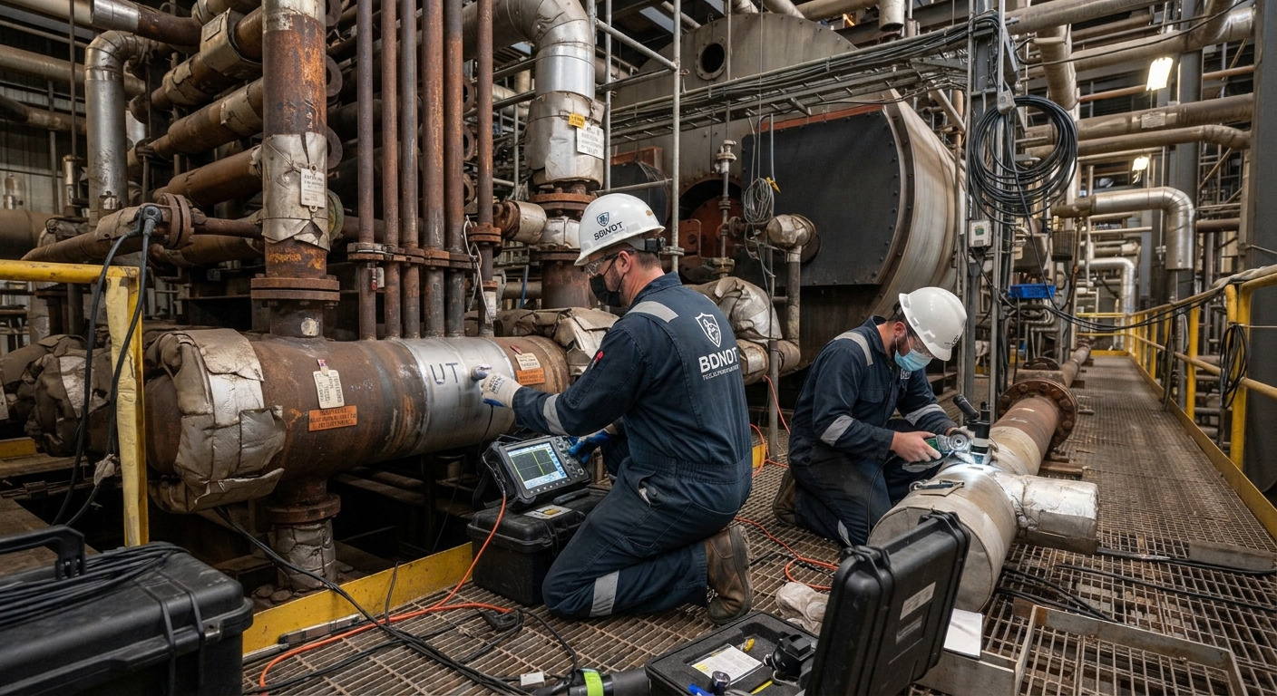
active creep swelling. - TASK 2: ULTRASONIC THICKNESS GAUGING (UT) – Establish a systematic grid pattern
across the water walls, superheaters, and bends. Execute ultrasonic thickness measurements to
calculate localized material loss from internal corrosion or external erosion. Deploy specialized,
high-frequency ultrasonic longitudinal probes on superheater and reheater tubes to measure
internal steam-side oxide scale thickness without cutting the tubes. - TASK 3: SURFACE DEFECT DETECTION (WFMPI / DP) – Perform Wet Fluorescent
Magnetic Particle Inspection (WFMPI) or Dye Penetrant (DP) testing across critical structural
welds, including drum circumferential/longitudinal seams, header stubs, nozzle joints, and safety
valve attachment welds. Evaluate all high-stress heat-affected zones (HAZ) to identify the
presence of surface-breaking thermal or mechanical fatigue macro/micro-cracks. - TASK 4: IN-SITU METALLOGRAPHIC REPLICATION – Grind and polish selected spots to
a mirror-like 1-micron surface finish using progressively fine diamond abrasive compounds. Apply
a localized chemical etchant (2% to 5% Nital solution) to reveal underlying metal grain
boundaries. Apply high-quality cellulose acetate replication film activated by an organic solvent to
pull a structural impression of the grain matrix. Mount onto glass slides for optical examination. - TASK 5: PORTABLE HARDNESS TESTING – Perform rebound (Leeb) or ultrasonic contact
impedance (UCI) hardness measurements on header shells, main piping, and associated weld heat
affected zones. Low hardness numbers indicate localized thermal softening or creep degradation,
while abnormally high hardness indicates embrittlement. - TASK 6: TUBE WINDOW SAMPLING & LABORATORY DESTRUCTIVE TESTING –
Cut a physical ‘window sample’ tube piece (minimum 300mm to 500mm in length) from the
highest heat-flux zone. Weld an approved replacement tube spool in its place using a qualified
welding procedure specification (WPS). Perform laboratory chemical cleaning and weight-loss
analysis to calculate the internal deposit density (g/m²). Machine laboratory specimens to run
mechanical tensile tests and accelerated stress-rupture tests under controlled high temperatures.